
The RHE monocoque models that use a Ford Sierra donor all use the whole Sierra rear subframe, final drive, springs, shock absorbers, and braking. If you built your Exmo then you will be familiar with the unit shown in the drawing and have experienced the challenge of fixing it squarely in the correct position under your shiny bodyshell. The features are a differential that is mounted on the subframe, which reduces unsprung weight, and independent wheel hubs mounted on "trailing arms" that pivot on the subframe with a coil spring between the trailing arm and body. The verticaly mounted shock absorber is mounted between the wheel hub and the body, when the body is raised the trailing arms drop and the springs are prevented from becoming loose by the shock absorbers reaching their maximum extension.
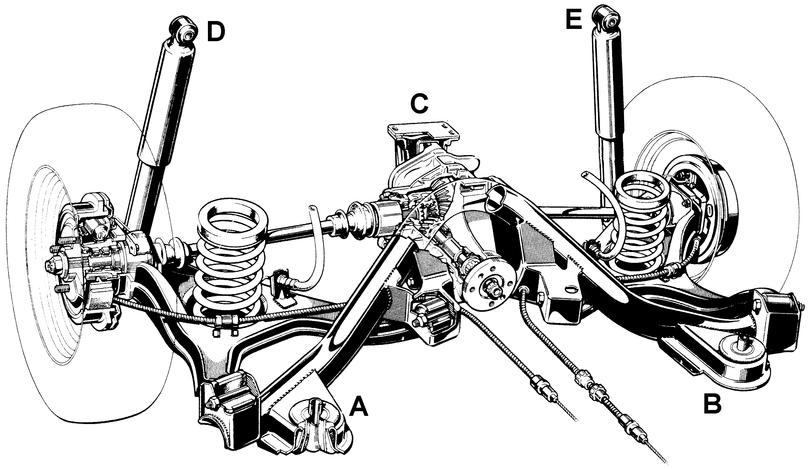 On the Sierra, the subframe is not solidly bolted to the body. It is attached via rubber mounts
in five places, A,B,C,D and E in the diagram. A and B are large "bagels" held in hollow lobes that
are welded to the leading edges of the tubular part of the subframe. C is an inverted yolk that
envelops a peg that is fixed to the top of the differential casing. The top of the yolk is bolted
using four rectanularily arranged bolts to the body. D and E are the tops of the verticaly mounted
shock absorbers, thus the tubular subframe and everything
attached, differential, trailing arms, driveshafts, brake drums etc can move slightly in the rubber,
absorbing vibrations leading to a quieter driving experience.
On the Sierra, the subframe is not solidly bolted to the body. It is attached via rubber mounts
in five places, A,B,C,D and E in the diagram. A and B are large "bagels" held in hollow lobes that
are welded to the leading edges of the tubular part of the subframe. C is an inverted yolk that
envelops a peg that is fixed to the top of the differential casing. The top of the yolk is bolted
using four rectanularily arranged bolts to the body. D and E are the tops of the verticaly mounted
shock absorbers, thus the tubular subframe and everything
attached, differential, trailing arms, driveshafts, brake drums etc can move slightly in the rubber,
absorbing vibrations leading to a quieter driving experience.
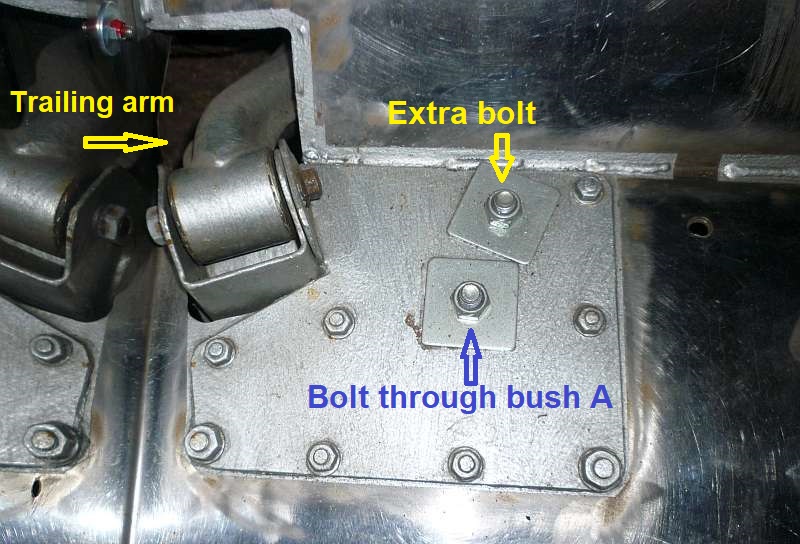
On the Exmo, the subframe is partly bolted directly to the body. Two thick roughly rectangular steel plates are placed left and right on the floor just forward of the sloping section behind the seats. As provided in the kit the plate has a pre cut central hole and a verticle portion formed by bending (see photo above). The vertical portion has a pre cut hole. When the subframe is attached the existing holes through the rubber bushes (A and B) line up with the pre cut hole in the centre of the plates, and an M12 high tensile bolt is used to attach. At the same time the pre cut hole in the verticle portion should line up with the hole through the bush and two flanges that form the outer pivot of the trailing arm. A long M10 bolt which goes through each flange, the bush, and the vertical section of the plate is tightened up. Notice that this connection solidly fixes the subrame to the Exmo body. Meanwile at point C four bolts fix the rear yolk to the Exmo body as per Sierra.
It will not have escaped your attention that the mountings at A and B can move slightly, while the outer trailing arm pivots are fixed. In theory therefore there might be some flexing of the vertical section of the plate, which just might lead to metal fatigue. This point was picked up by some SVA testers, leading to RHE asking owners to drill another hole in the plate, and through the hollow lobes. The lower hole in the lobe is enlarged to allow a nylock nut to be placed on an M12 bolt that goes through the plate and top of the hollow lobe. The owners were instructed to make sure that this bolt is very tight.
Nothing was said about the remaining rubber yolk bush attachment at the differential. After this modification the need for bolts through the rubber donuts at A and B is eliminated, however most builders will have retained them, if only to stop water ingress.
There may be some Exmos about that do not have this modification, there have been no reports of metal fatigue with the original fixing.
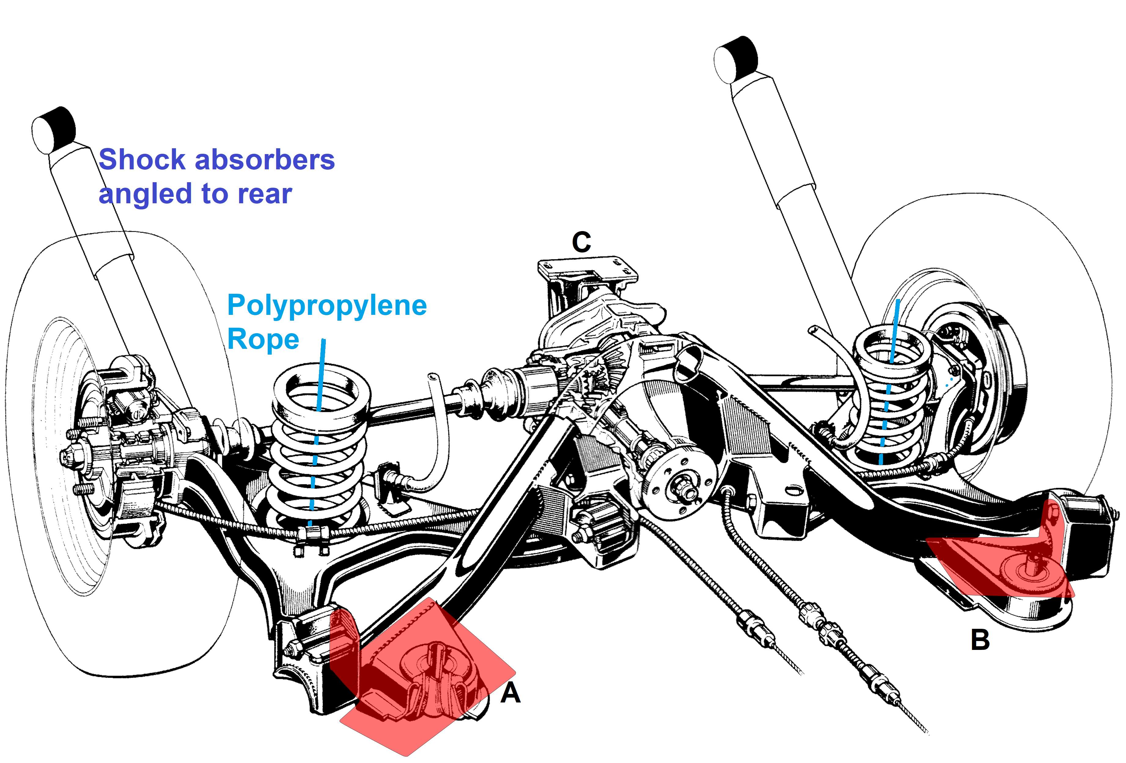
Frequently, original Exmo owners are not happy with the spring and shock absorber from the Sierra. The proximity of he Exmo body to the wheel hubs means that the long Sierra shock absorbers are mounted at 45 degrees(ish) towards the rear, using a bolt welded to the top rear quarter for the top bush. This has a big disadvantage, in that the trailing arm is no longer prevented from dropping down low enough for the spring to pop out from the "jaw" between the body and the depression in the trailing arm. The RHE solution was to thread some polypropylene rope (provided in the kit) through the existing spring, fixed top and bottom using eye bolts, and just the right length to prevent the spring getting loose.
Towards the end of production RHE offered a "coil over" option which some builders purchased. Throw away the Sierra shocks and springs. Fit coil over shock absorber units between the original mounts at the wheel hub and the large angle iron section that is above. The angle iron, which is used to secure the main monocoque to the adjustable rear section, is only xxx mm wide, so the fitting is "tight". I believe that this coil over option was not made up from off the shelf parts. (to be checked).